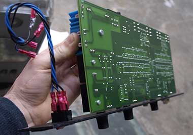
If you own like us one of the first versions of this beautiful device you might also have noticed that when you plug some balanced source (that share energy between hot and cold signals) in it you get a -6db level drop, indeed these versions of the SPL transient designer have unbalanced ins and outs. But they were kind enough to put balanced jack connectors which will make it easy for us to modify the inputs and making them balanced which will solve all of our level drop problems!
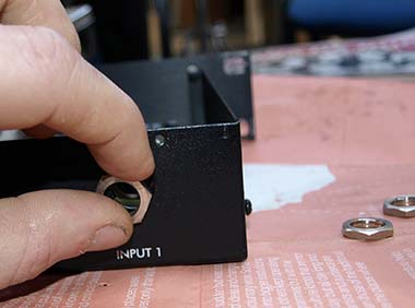
First of all you need to unscrew the top cover of the unit, then the hex nut on the in/out jacks.
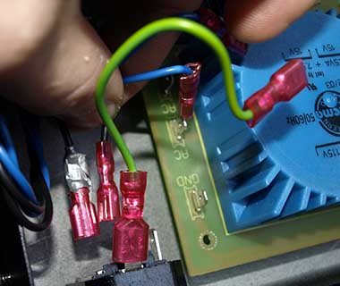
We'll have to remove the power connectors.
Remove the allen screws from the front panel.
And the silver screws holding the pcb to the unit.
Here we are, don't be as lazy as us unscrew the pot's knobs & nuts and remove completely the front panel, otherwise you might damage the pots...
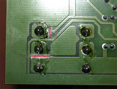
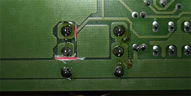
Now some traces to cut, on the input#1 jack.
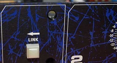
And the 2nd input.
Then on the 1st TL072.
And on the 2nd TL072.
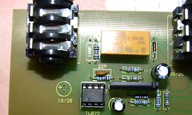
A cap and a resistor to remove on the input #1 side. And also remove the two TL072 from their sockets and put some NE5532 instead.
Still same thing on the other side.
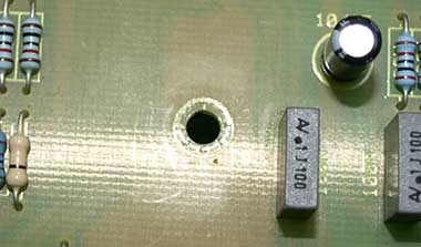
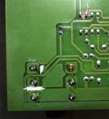
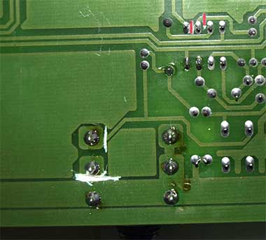
Now 6 small holes to drill...
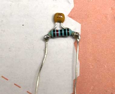
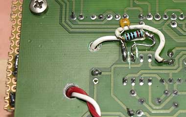
We have to solder a pair of 10k resistors with a 22p cap in parallel.
Put them at the place of the 100k resistor removed previously.
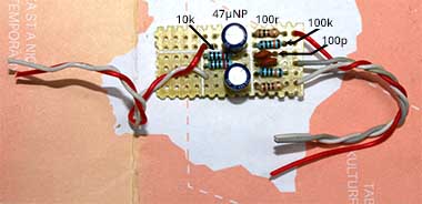
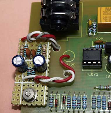
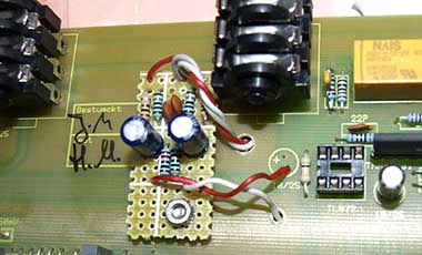
Now let's solder on a veroboard some components, a pair of 100 Ohm resistors, 100K, 10K, 100p and 47µ bipolar caps, 3 wires at one side , 2 wires at the other side.
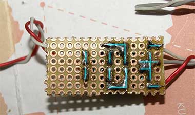
Here's how it goes the other side, with thoose 2 pics you should be able to reproduce it.
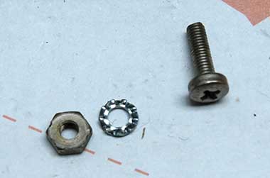
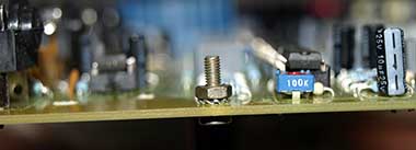
We need now a pair of M3 screws with a washer and a nut.
Put it in the hole you drilled which is the closest to the left side of the pcb.
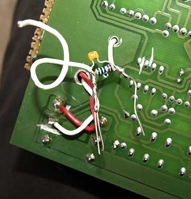
Put the 3 wires in the hole just like you see on the picture, solder the red wire on the "-" side of the cap you removed previously, and put the white wire in the remaining hole, just as on the picture.
Now you can prepare another pair of 10K resistors paralleled with a 22p cap, and solder a piece of wire at one side. The grey wire doesn't appear on the pic, I fogot it when I took the picture, but you should have this 3rd wire and solder it on the ground, you'll see it on further pics!
Solder the remaining side of the 10K/22p to the white wire you've put through the hole.
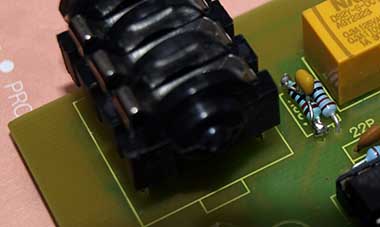
Solder the stuff at the back on the TL072 just as on this picture.
Then solder a 100 Ohm resistor across the center pins of the relay and solder a wire between this resistor and the components you have put at the back on the TL072 as you see on the picture.
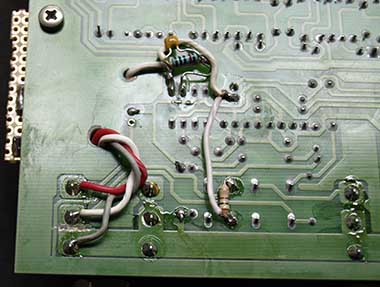
Same thing for the 2nd input's side.
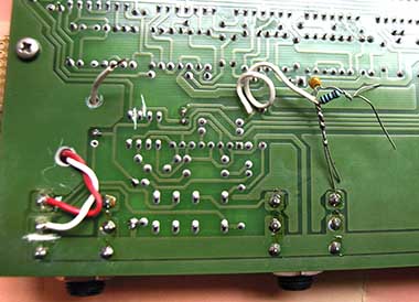
Backward.
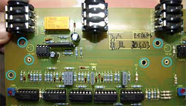
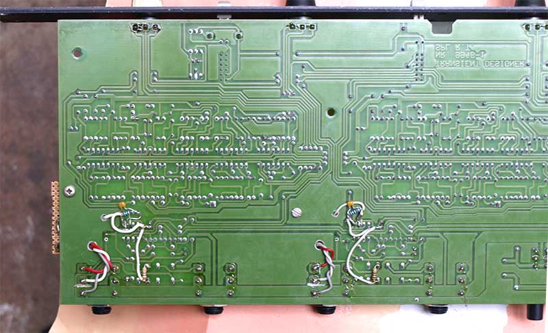
The whole stuff seen from the back of the pcb.
You can put a bit of tape to make sure you don't have any contact between the chassis' ground and your components, but the spacers should be high enough anyway.
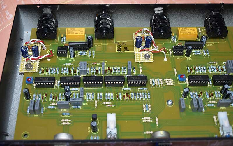
Here's how the whole thing should look like at the end.
Basicaly we went from something like this :
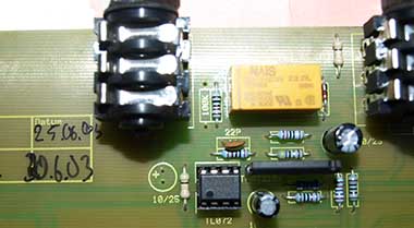
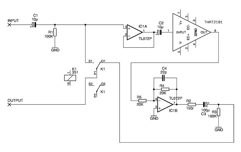
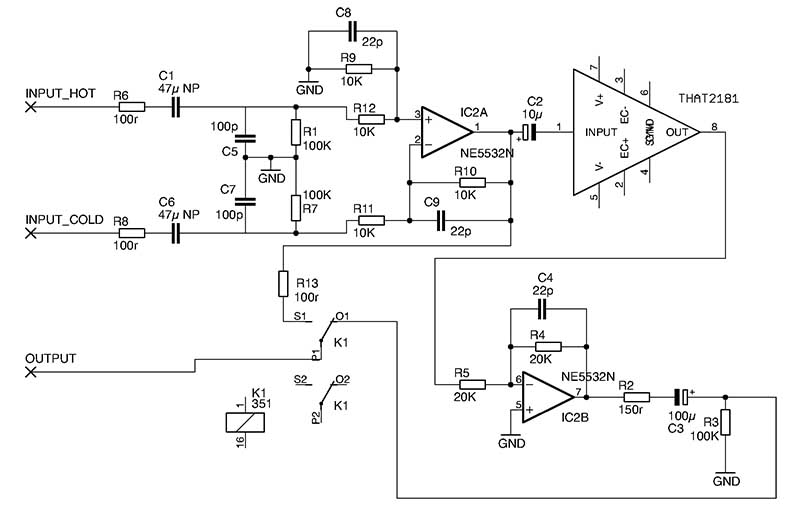
To something like that :
The balanced input stage comes from Douglas Self's book Small Audio Design which we highly recommend the reading of... You can choose to stay with the TL072 and not to replace them with the NE5532, then replace R9 R10 R11 and R12 by 100K resistors, you can even avoid to unsolder the 100K resistor, but it is always better for CMRR to match thoose resistors if you can. For the bypass we decided to use the output of the differential op amp without AC coupling it because the offset voltage was extremely low.
One last thing to do is to check the polarity of C2 and C3, I had to reverse some and some other not.. if you measure a postive voltage when you put the "-" side of your voltmeter on the "-" pin of the cap and the "+" side of the voltmeter on the "+" pin of the cap then the cap is in the right direction, if the voltage is negative then you have to solder the cap in the opposite direction.
It looks like there are no bypass capacitors on the supply pins of the op amps, it could be interesting to measure with an oscilloscope if we have some HF psu noise and if some bypass caps would reduce it, but I didn't do it.
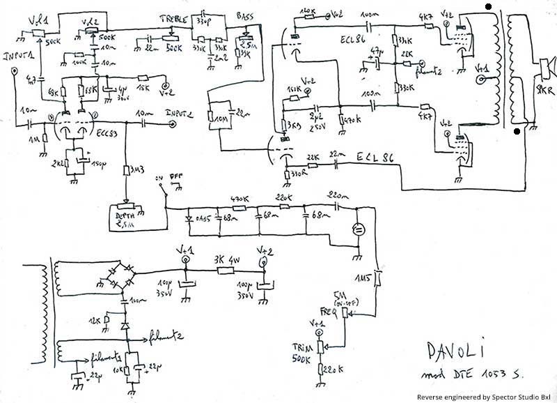
Davoli Special Tube guitar amplifier - Mod DTE 1053 S
This is a beautiful tube guitar amplifier from the 60s, we had the amplifier head without the cabinet, so we put it in an old Carvin combo (SX-100, I think...) which head was wasted, the Carvin combo had a good speaker and the combination of the two is very sweet, it reminds a lot of like Creedance Clearwater Revival guitar sound and the tremolo is amazing!
We had to make some reverse engineering to restore this amplifier, so here is the schematic if it can help anyone :
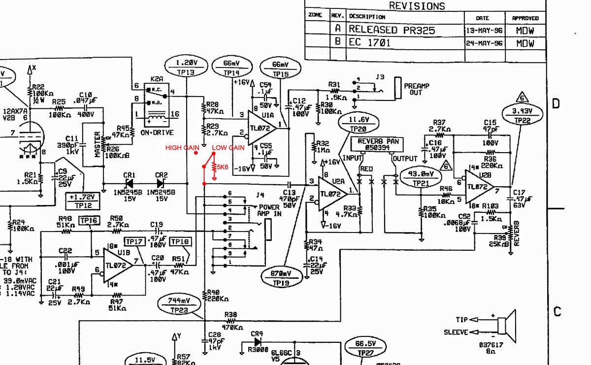
Fender Hot Rod Deluxe low gain mod.
The Hot Rod Deluxe is a great amp but it's often too loud even on stage, and it's very difficult to get the right level on the volume pot between steps "1" and "2"... You can find many tutorials to change the 12AX7 preamp tubes with some 12AT7 which have less gain or with some 12AU7 for even less gain, it's probaly a very good solution, but if you don't want to change your tubes and always get the possibility to get very high gain, you can do you like us and add a simple switch which will give you something like -19db of attenuation which should be perfect to adjust the right level easily, all you need is an on/off switch, a 5K6 1/4W resistor an a bit of wire.
Very simple as you can see, we didn't take pics but you should figure easily where to solder this resistor and where to add a switch (we drilled a little hole underneath the "PREAMP OUT" and "POWERAMP IN" jacks to put the "low gain" switch). This mod works well, we use our modded amp for 3 years without any problem, it doesn't imply any frequency shift and doesn't change the sound of the amp.
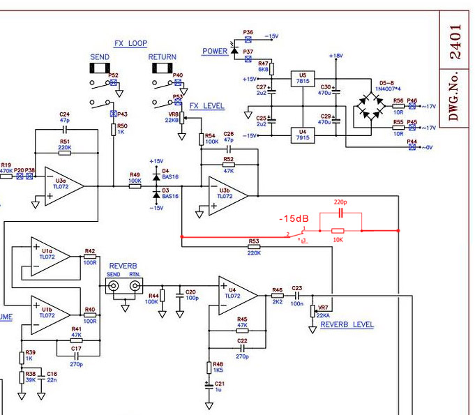
Laney VC 30 low gain mod.
Here's what we did to add a -15dB switch to use the Laney VC30 guitar amp combo at a lower volume, because it has quite a high gain and it can be good in some circumstances to get some crunsh at a lower volume and adjust the gain and level more comfortably.
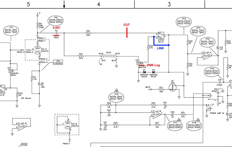
Fender Blues Deluxe / Blues Deville Master pot mod.
The purpose of this mod is to use the Master potentiometer on the clean channel without changing the sonic charactere of this amplifier. It will let you operate the Volume control of the clean channel with a more comfortable range and you'll be able to get some crunch at a lower overall level. The Master pot will still act on the "Drive" channel as well.
It has been tested succesfully on a Blues Deluxe Reissue and should also work on a Blues Deville.
You should easily find online the original schematic, and here's the modification :
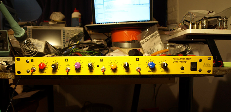
Amek 2500 Funky Preamps.
The mic preamps from the Amek 2500 mixing desk are some very nice and efficient preamps that will not cost you much to make. We did build a 4 pieces' rack with a volume stage and a balanced output and we share here the PCBs to help the DIYers from around the world who would also like to build these preamps.
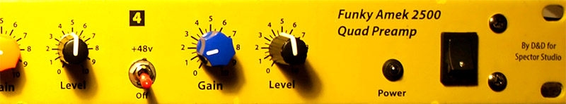
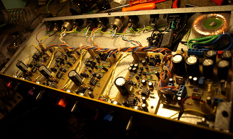
Here is our charming and funky rack :
As we try to fight against programmed obsolescence, global waste and we generally try to recycle as many things as we can, the box comes from an old video processing rack we bought 1€ at the legendary "Jeu de balle" flea market in Brussels :
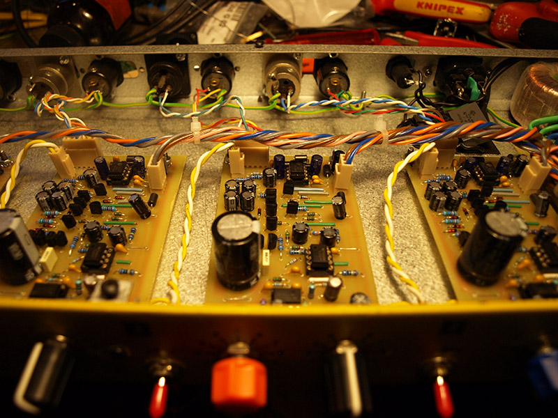
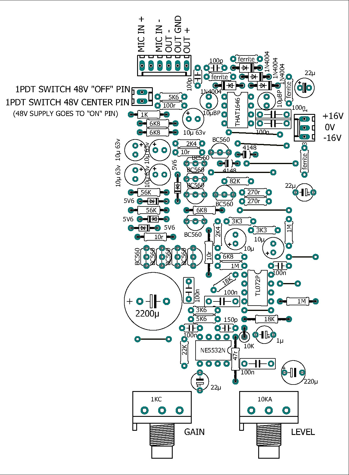
Here are the boards nicely set-up :
With the 2x 16VDC PSU + 48V phantom power :
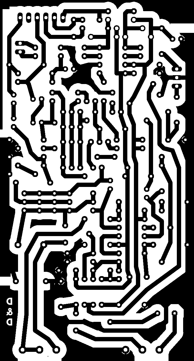
And last but not least, the drawing to etch your single side PCBs :
Electrolytic capacitors :
1x 1µ 35V or higher
2x 10µ Bipolar 35V
7x 10µ 63V or higher
3x 22µ 35V or higher
1x 220µ 35V or higher
1x 2200µ 6V3 or higher
Diodes :
2x 1N4148
4x 1N4004
4x 5V6 zener
Transistors :
10x BC560C
ICs :
1x NE5532
1x TLO72
1x THAT 1646
Switchs :
1x SPDT ON-OFF or ON-ON Switch if you use 48V phantom power
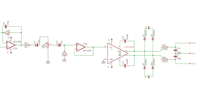
And if you mind, the output and volume stage schematic :
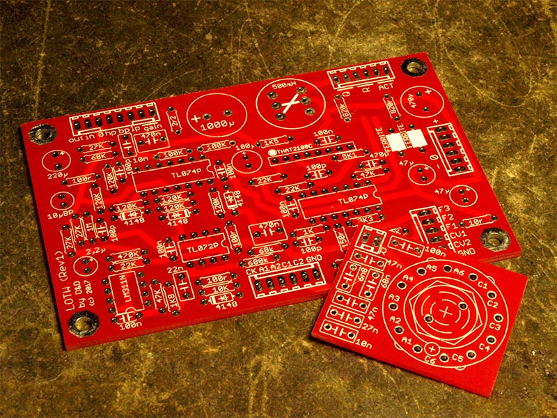
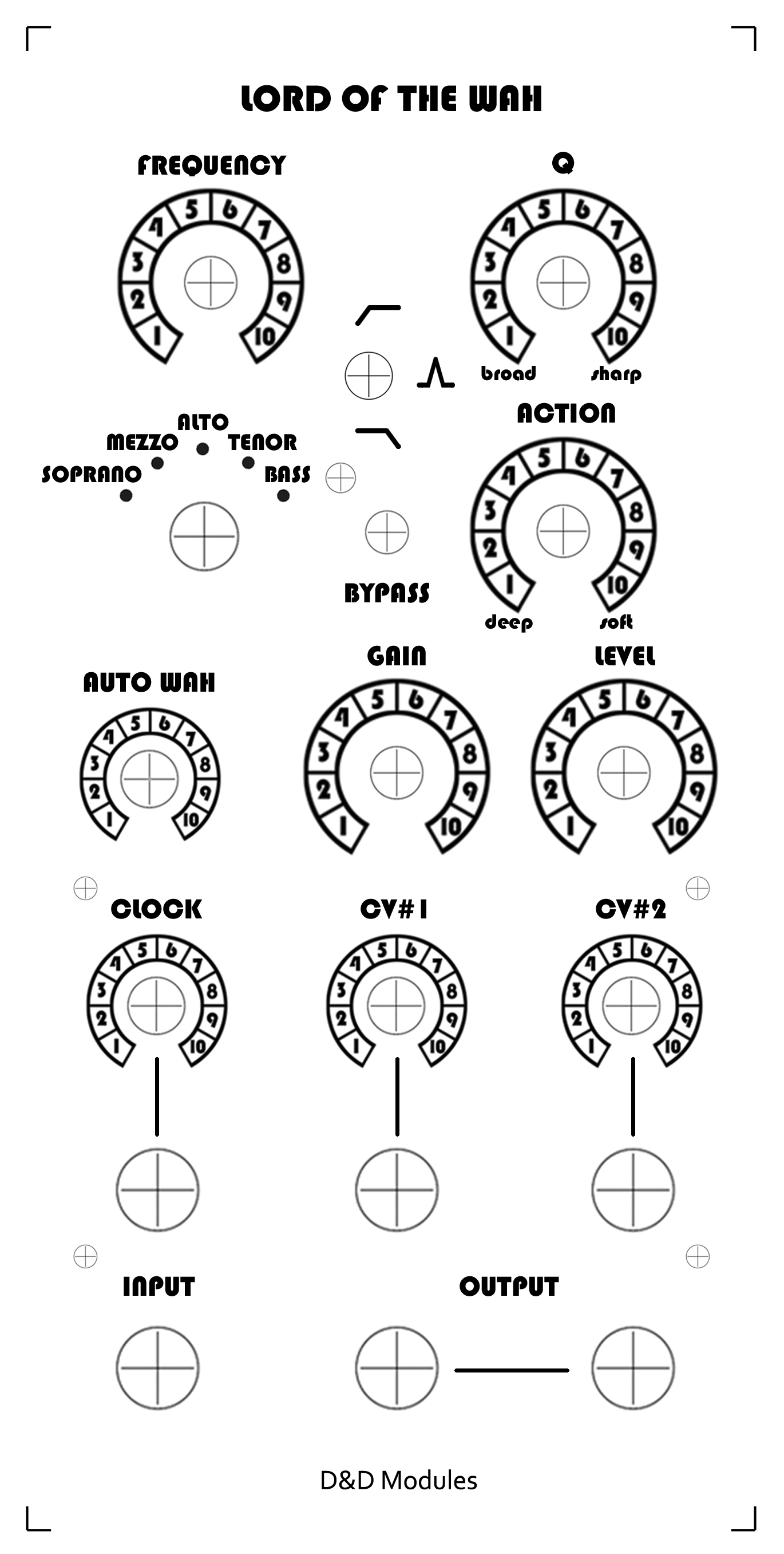
Lord Of The Wah - A voltage controlled Wah Wah for modular synthesizers.
We had since a long time, like lots of other people, the idea of making a VC Wah, , watching the documentary "Cry Baby: The Pedal that Rocks the World" convinced us to really do it.
This great article about the Technologie of Wah pedals really helped, thanks to the guy who wrote it! Geofex Technologie of Wah pedals
Here's a demonstration video showing the kind of sounds you can get with it
For DIYers :
Send us an email at order@sub-continental.com if you're interested in purchasing a PCB :
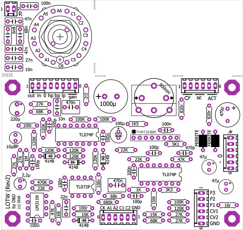
Electrolytic capacitors, all rated for 35V or higher :
1x 2,2µ
1x 10µ Bipolar
2x 47µ
1x 100µ
1x 220µ
1x 470µ
1x 1000µ
Diodes :
4x 1N4148
1x 3mm Red LED
ICs :
1x LM311
1x TLO72ACP
2x TL074
1x THAT 2180C
Switchs :
1x SPDT ON-OFF-ON toogle switch
1x DPDT ON-ON Sub-mini toogle switch (the ones that are even smaller than standard toogle switchs)
1x MBB (make before break/shorting) Rotary Switch 2P6T with PCB pins, used in 1P5T configuration
Jack & led sockets :
6x Mono 6,35" Jack sockets
1x 3mm led socket
Potentiometers :
1x 5K REV LOG (Solid Shaft for using the same knobs as us)
5x 100K LIN (for using the same knobs as us : 1x Solid Shaft, 4x Split Shaft)
3x 100K LOG (Solid Shaft for using the same knobs as us)
Knobs suggestion :
5x Eagle knobs 19mm fluted for solid shaft pots
1x Davies 1510 knob for solid shaft pots
4x Knobs with a diameter between 12 and 14mm, fiting split shaft pots
Optional connectors :
4x 6-pins molex or equivalent 2,54mm spacing
1x 8-pins molex or equivalent 2,54mm spacing
*************************
****** SPECIAL NOTE ******
*************************
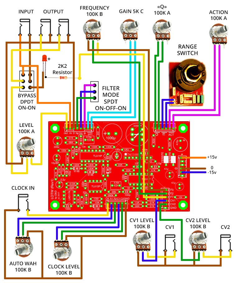
+/-12V Operation :
This module is conceived to work with a +/-15V PSU, but for +/-12V operation it should work with these modifications :
- near the connector with "F3 F2 F1 CV1 CV2 GND" you have 4 resistors : "100K 120K 27K 27K" > the 120K should be replaced by a 100K resistor
- at the left of the bord near "LOTW (Rev1)" you have 3 resistors "27K 27K 1M" > the 27K in the middle should be replaced by a 22K
- and finally the 1K8 resistor near the LM311 IC should be replaced by a 2K2 resistor.
Comming soon..
Comming soon..
Comming soon..
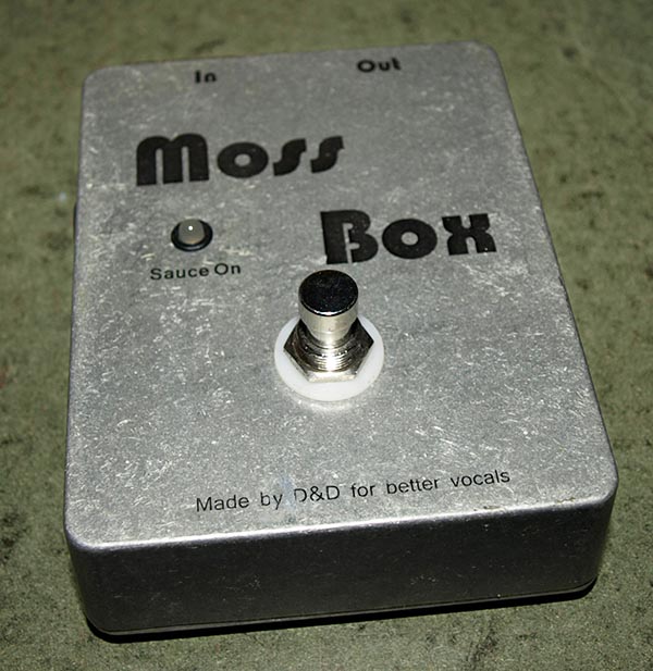
The MossBox, a vocal boost.
Actually it's not a boost but a passive attenuator, thanks to Gyraf from groupdiy for the idea, and especially thanks to AbbeyRoaddEnfer from the same forum for giving the idea to use a U-pad which shunt part only would be switchable, making possible the use of a simple 2PDT footswitch instead of a 3PDT MBB footswitch which apparently doesn't exist.
So the 'off' position is when the pad is active and the 'on' position is when the pad is inactive.
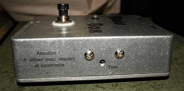
We added a trimmer to be able to ajust a bit the amount of attenuation, or the amount of boost if we think backwards.
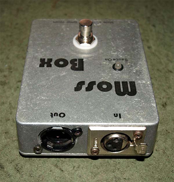
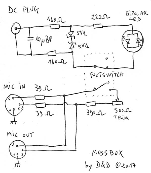
As we all know Moss is so technologically dumb that he could burn a whole city trying to plug something in the wrong hole, that's why we used a bipolar led with 2 zener diodes so that the use of any AC adapter is possible!
As somebody said "it sounds like a recipe for feedback from stage monitors", it's true somehow, the box must be 'on' during the very beginning of the soundcheck and as it only boosts for few DBs it doesn't make any problem in real live conditions but of course you should not balance the voice level close to larsens with the MossBox 'off'.
Here are some few pics :
There are so few components that you don't really need a PCB, you can simply use the point to point wiring technique, here's the schematic :
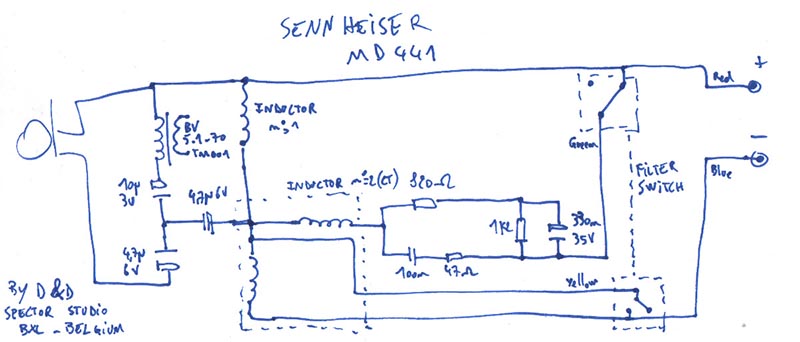
Sennheiser MD 441 Circuit diagram
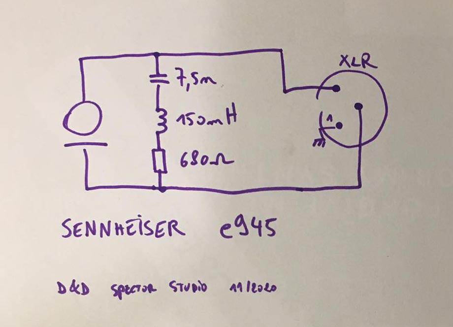
Sennheiser e945 Circuit diagram
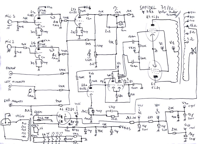
Safidel 3120 amplifier circuit diagram
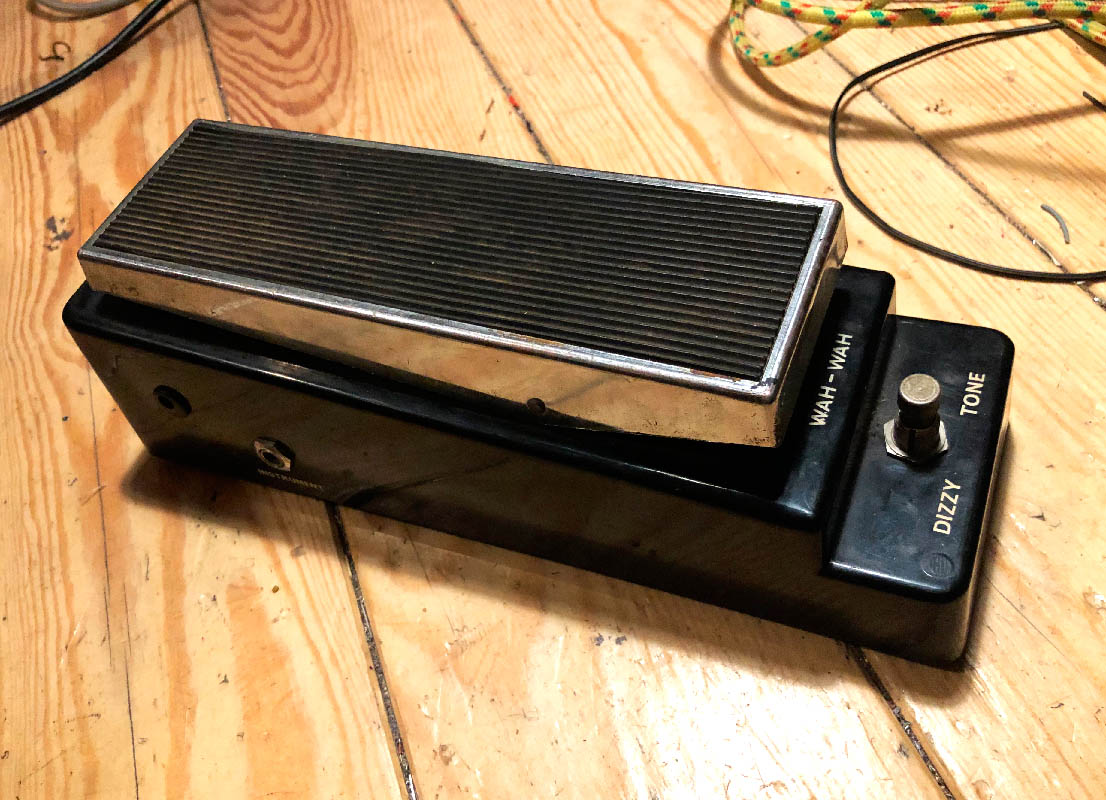
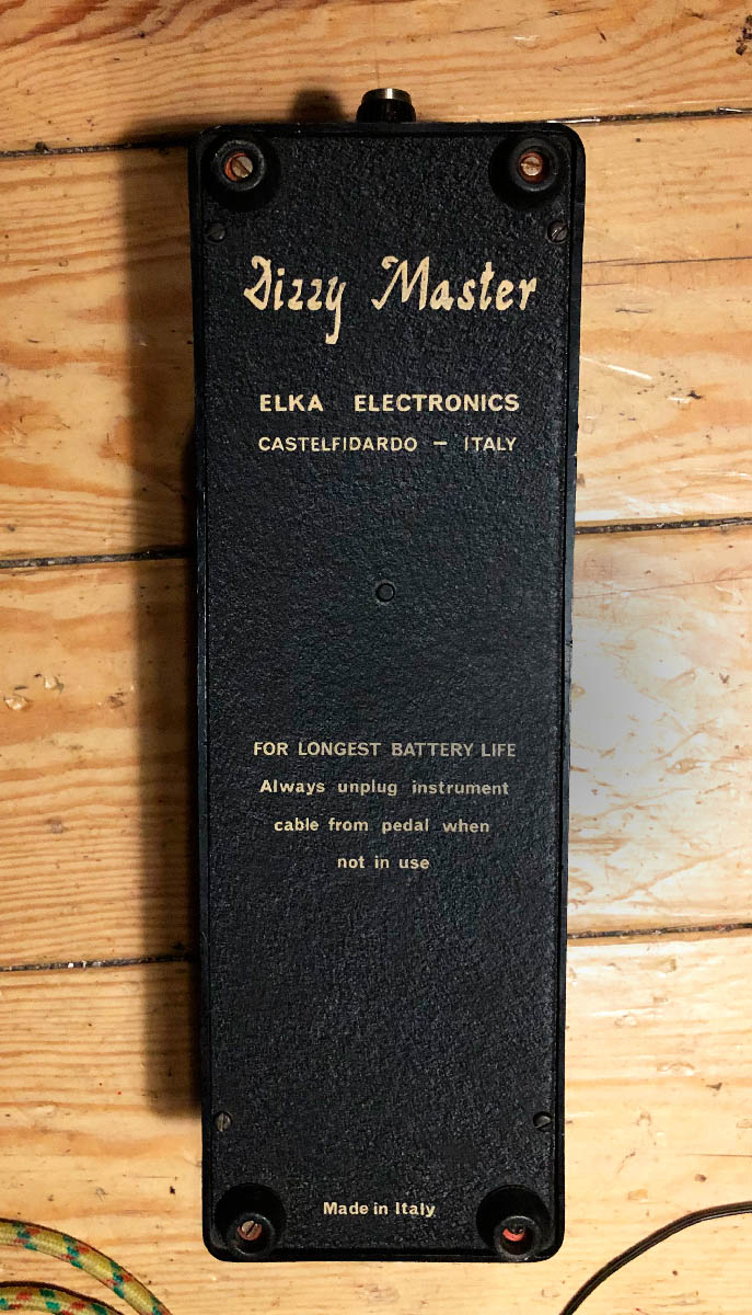
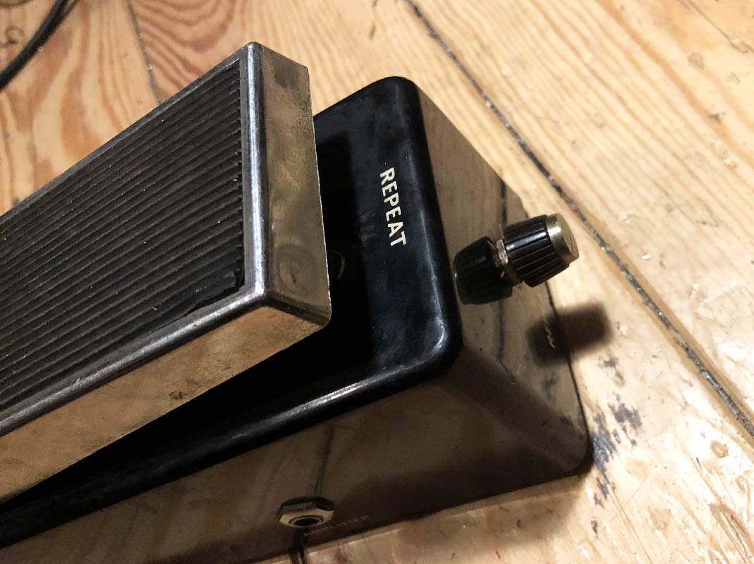
Elka Electronics' Dizzy Master - Schematic and modification
The Dizzy Master is a guitar pedal from 1967, there's a clone of the very first wah that was released one year before by Vox, there is also a very chopped tremolo that almost sounds like a delay, of course it is not a real delay because it was impossible to make an echo with anything else than a tape player and recorder at that time. There is also a very mighty fuzz called "Dizzy Tone".
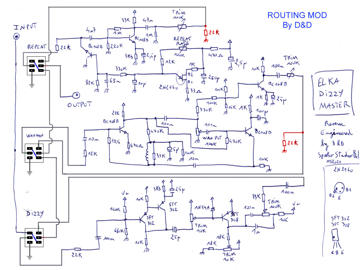
Here's the Dizzy Master's schematic :
The three effects, the tremolo, the wah-wah and the fuzz are routed in parallel. We found more interesting to chain them in series like that : fuzz first, going into the wah, going into the tremolo, true-bypass each time, to do this mod, you only have to add two 22K resistors and a bit of re-wiring, and then to adjust few trimmers for unity-gain.
Here's our mod's schematic :
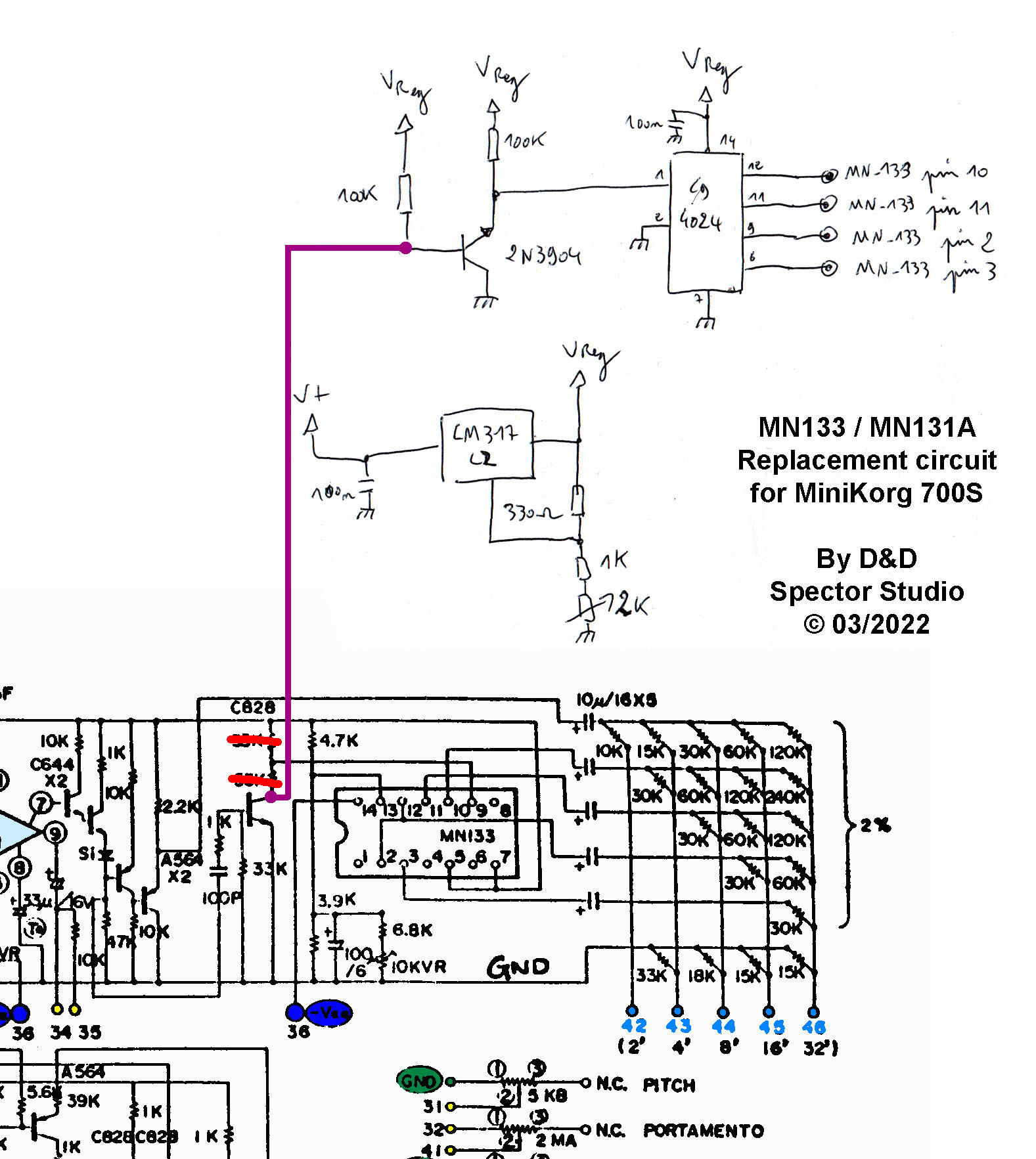
MN133 - MN131A substitute circuit for MiniKorg 700S
MN133 and MN131A are very rare and obsolete frequency divider integrated circuits, they are very difficult to find or at an insane price.
Here's a little substitution circuit that will allow you to make your MiniKorg 700S synth octave divider work again with a CD4024BE IC and few transistors. You will have to unsolder and remove the MN133 (or MN131A) from the board, to remove the two 33K resistors (crossed out in red on the schematic) and to wire the circuit as indicated. The 2K trimmer for the LM317LZ adjustement will allow you to trim the right sawtooth waveform for all the octaves.
One last important thing is that you need to use a shielded wire for the signal that is drawn in purple in the schematic.
The Manual (How to Have a Number One the Easy Way) - KLF
KLF's situationist masterpiece translated into French, TOTP unfortunately no longer exists, and times have changed, but many mechanisms are still the same. In any case we hope this manual will amuse you as much as it will open your mind.
 Français